Projects / Electronics · Prototype
Mini
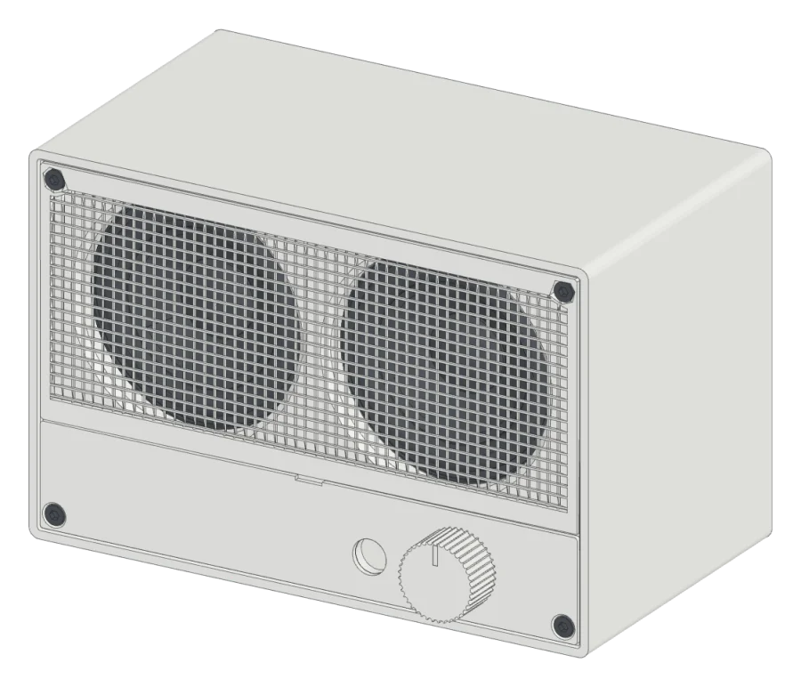
A Braun-style Bluetooth desk speaker with two 2.5-inch drivers and a printed snap-on grille.
- Size
- 166 × 108 × 94 mm
- Drivers
- 2 × 2.5 in
- Box
- Sealed, 1.1 L
- Skill
- Intermediate
Overview
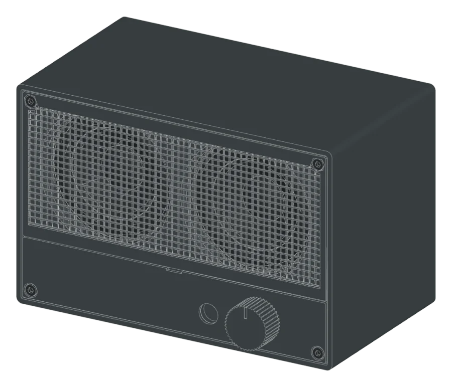
The Mini is a small stereo speaker for a desk. It has a grey sleeve, an orange baffle that shows through a fine grey grille, and a white control strip with an orange knob.
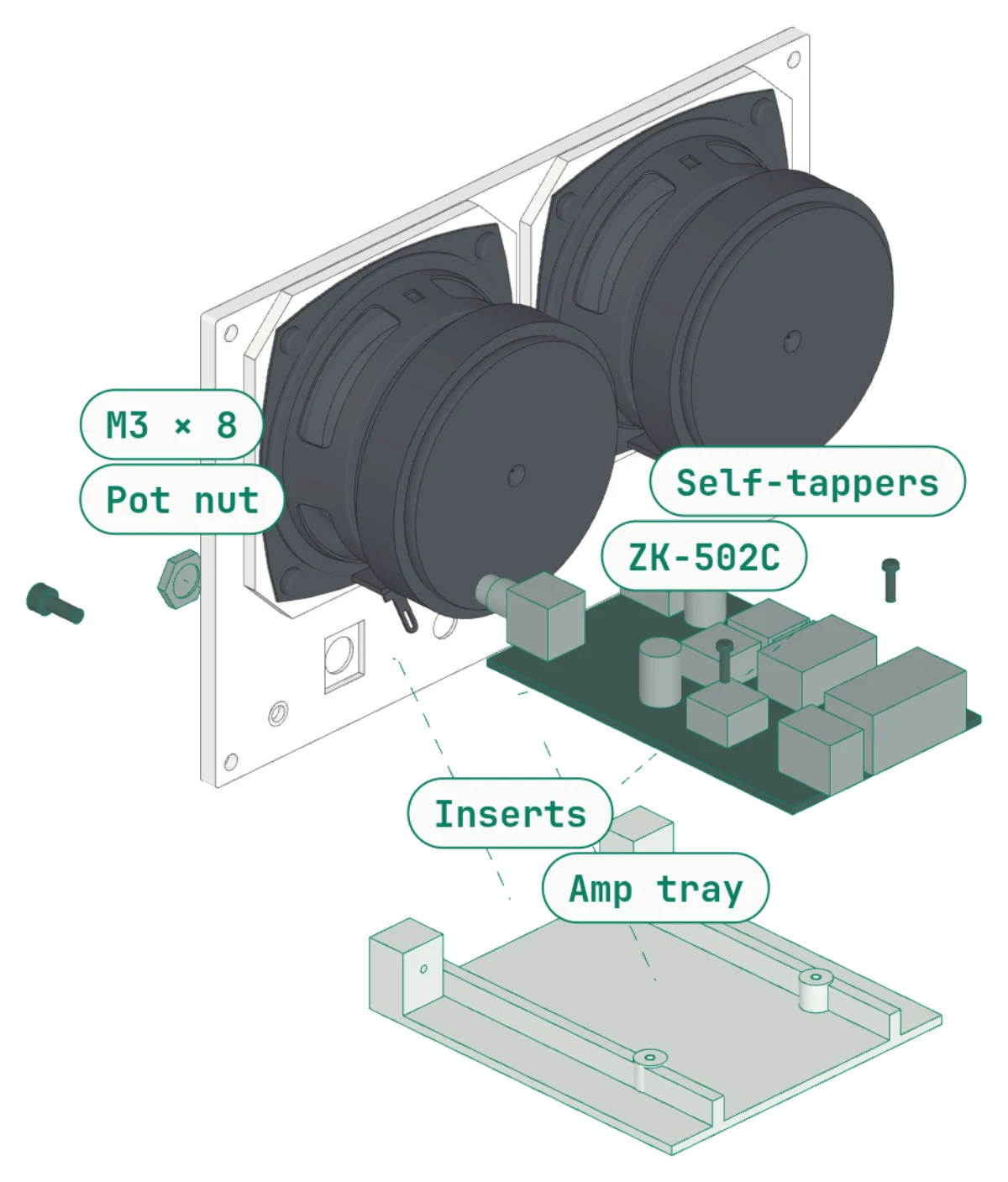
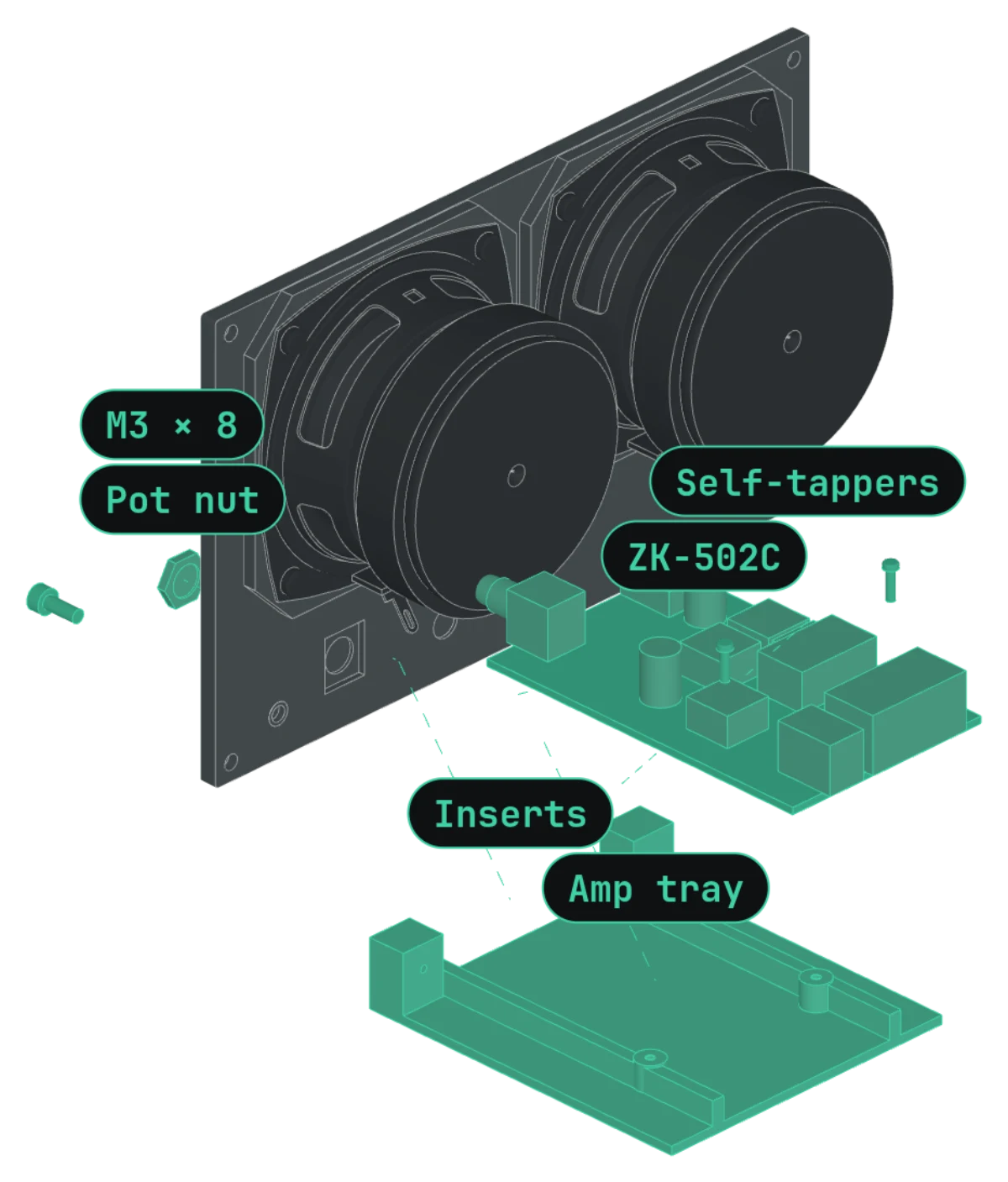
A ZK-502C board does the Bluetooth, the amplifier, and the volume control in one part. It lies flat on a printed tray behind the baffle. Its volume control and AUX socket come out through the front, and the DC socket lines up with a hole in the rear panel.
The baffle, the drivers, the tray, and the amp form one front module. It slides into the sleeve and is held by four screws. The grille and the strip then snap on over the screw heads.
Each PC68-4 sits in about 0.55 L of sealed air. That gives a Qtc near 1.0 and an F3 near 150 Hz: clear mids and little deep bass, which suits a desk speaker.
What you need
| Part | Qty | Type | Get it |
|---|---|---|---|
| Sleeve Grey, front opening down, supports under the 4 front posts only | 1 | Download | |
| Front baffle Orange, front face down, no supports | 1 | Download | |
| Rear panel Grey, outer face down | 1 | Download | |
| Amp tray Grey, flat | 1 | Download | |
| Grille Grey, front face down, Grille profile | 1 | Download | |
| Control strip White, front face down, about 9 g | 1 | Download | |
| Knob and mark Orange knob, white mark glued in | 1 | Download | |
| Feet Grey, or use stick-on rubber feet | 1 | Download | |
| Dayton Audio PC68-4 driver 2.5 in full range, 4 Ω | 2 | Buy | Parts Express ↗ |
| ZK-502C Bluetooth amplifier board Bluetooth, volume pot, AUX in, 12–24 V DC | 1 | Buy | Amazon search ↗ |
| DC power adapter, 12–24 V, 2 A or more Check the plug size of the ZK-502C socket before you buy. | 1 | Buy | Amazon search ↗ |
| M3 heat-set inserts, short 3 mm long, 4.0 mm hole | 18 | Hardware | CNC Kitchen ↗ |
| M3 × 8 socket head cap screws ISO 4762. Baffle 4, tray 2. | 6 | Hardware | Amazon search ↗ |
| M3 × 6 socket head cap screws Rear panel | 4 | Hardware | |
| M3 × 5 pan head screws Drivers | 8 | Hardware | |
| Self-tapping screws, 1.9 × 7 mm 3.28 mm pan head. Board to the tray posts. | 2 | Hardware | |
| Speaker wire, 2 × 0.5 mm² | 2 × 150 mm | Hardware | |
| Closed-cell foam tape, 3 × 6 mm Driver flanges and panel seams | 0.6 m | Hardware | Amazon search ↗ |
Tools
- 3D printer — Bed at least 170 × 100 mm. The profiles target a LulzBot TAZ Workhorse with a 0.5 mm nozzle.
- Soldering iron with an insert tip — For the 18 heat-set inserts
- Drills, 3.4 mm and 4.0 mm — For the pilot and insert holes
- 2.5 mm hex key — For the M3 socket head screws
- Flat blade — To pry the covers off later
Print settings
- Material
- PLA in grey, orange, and a little white
- Nozzle
- 0.5 mm (the grille ribs are one line wide)
- Temperature
- 220 °C
- Horizontal expansion
- 0.095 mm on the shell and parts. None on the grille.
- Supports
- Only under the four front posts of the sleeve
- Fit test
- Print the three snap coupons first to check the catches
Build it
Drag to turn · scroll to zoom · right-drag to pan
-
01
Print the parts
- Print the three snap fit-test coupons first. Check that each one clicks and holds.
- Print the sleeve with its front opening down. Add supports under the four front posts only.
- Print the baffle front face down with supports off. Its front shows through the grille, so keep it clean.
- Print the grille with the Grille profile, which has no horizontal expansion.
- Print the rest flat, in the orientation of each STL.
Tip The colors come from the filament. No part needs paint.
-
02
Prepare the sleeve
- Remove the supports under the four front posts.
- Drill the four front post holes: 4.0 mm, 7 mm deep.
- Install 8 short inserts in the sleeve posts: 4 at the front and 4 at the rear.
- Glue the four feet into the recesses on the bottom.
-
03
Mount the drivers on the baffle
- Front baffle
- Dayton Audio PC68-4 driver
- M3 heat-set inserts, short
- M3 × 5 pan head screws
- Closed-cell foam tape, 3 × 6 mm
- Drill or cut the membranes in the baffle.
- Install 8 short inserts in the two spacer frames on the back of the baffle.
- Put foam tape on the front face of each driver frame.
- Set each driver on its spacer frame from the back, terminals down.
- Install four M3 × 5 pan head screws in each driver.
-
04
Fit the tray and the amp
- Amp tray
- ZK-502C Bluetooth amplifier board
- M3 heat-set inserts, short
- M3 × 8 socket head cap screws
- Self-tapping screws, 1.9 × 7 mm
- Speaker wire, 2 × 0.5 mm²
- Drill the two tab holes of the tray: 4.0 mm, through. Install 2 short inserts in the tabs.
- Hold the tray against the back of the baffle. Install two M3 × 8 screws from the front of the baffle into the tabs.
- Take the knob and the nut off the ZK-502C volume control.
- Set the board on the tray rails. Push the volume bushing and the AUX socket into their holes in the baffle.
- Thread the nut onto the bushing from the front. It pulls the pot body into its pocket.
- Install the two self-tapping screws through the rear holes into the tray posts. Stop when the head touches the board.
- Connect the speaker wires from each driver to the ZK-502C terminals.
Caution Do not tighten the self-tapping screws past snug. The thread strips the 1.5 mm plastic hole.
-
05
Install the front module
- Push the front module into the front of the sleeve.
- Install four M3 × 8 socket head screws through the baffle into the posts. The heads sit flush in their counterbores.
-
06
Install the rear panel
- Push the rear panel into the sleeve. The DC socket lines up with the hole.
- Install four M3 × 6 socket head screws.
-
07
Snap on the covers and the knob
- Line up the white strip with the two lower screw heads and the volume control. Push until the four catches click.
- Line up the grille ports with the two upper screw heads. Push until the four catches click.
- Push the knob onto the volume control shaft.
Tip To remove the covers, pull off the knob and pry at the slot on the top edge of the strip. Never pry at the center of the grille.
-
08
Pair and test
- Plug in the DC adapter. Pair your phone with the ZK-502C.
- Play a sweep from 80 Hz to 300 Hz at medium volume. Listen for rattles.
- Test the AUX input with a 3.5 mm cable.
Tip A rattle usually means a loose driver screw or a gap in the foam tape.
Downloads
- Sleeve (STL)STL
- Front baffle (STL)STL
- Rear panel (STL)STL
- Amp tray (STL)STL
- Grille (STL)STL
- Grille infill presets (Cura 3MF)3MF
- Control strip (STL)STL
- Knob (STL)STL
- Knob mark (STL)STL
- Feet (STL)STL
- Snap test, baffle (STL)STL
- Snap test, grille (STL)STL
- Snap test, strip (STL)STL
- Spec sheet (PDF)PDF
- Drawings, 12 sheets (PDF)PDF