Projects / 3D print · In progress
Pen Plotter
A table pen plotter from the parts of a Creality CR-10 V3. The stock control box runs new firmware in Go.
The design is complete and checked in software. It is not built yet.
- Travel
- 245 × 390 mm
- Printed parts
- 16 · 383 g
- Print time
- 21 h 45 min
- Parts to buy
- about $199
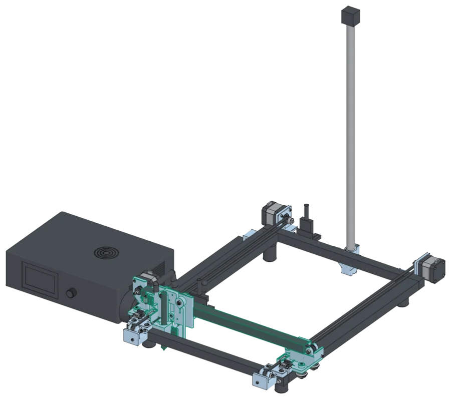
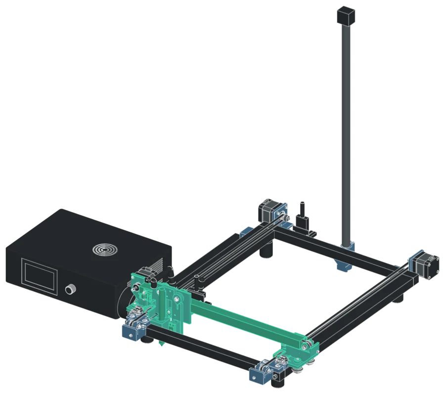
Overview
This plotter uses the base frame of a dismantled Creality CR-10 V3. The frame stands on the table, and the table is the bed. The paper lies on the table, and the gantry moves over it. A4 and Letter sheets fit.
Stock V-wheels carry both axes: three on each printed Y carriage, and three on the printed X plate. The motors do not move. Two Y motors stand behind the back bar and square the gantry when it homes. The X motor stands at the left end of the beam, and the X belt runs in the slots of the beam, as on the stock CR-10.
A hobby servo lifts the pen by 7 mm. The pen force is the weight of the pen slider and the pen. You change the pens by hand: at each M6, the plotter lifts the pen and waits. You put in the next pen and press the knob.
The stock control box drives the plotter. Its ATmega2560 runs new firmware, written in Go and built with TinyGo. The stock harness, the LCD, and the knob stay. A computer sends G-code over USB.
The printed parts copy the stock CR-10 layouts and keep only the features that the plotter uses. Each Y carriage is a flat 6 mm plate, in the form of the stock Z carriage plate. No step cuts or drills the metal of the frame.
Status: the design is complete and checked in the model and in the simulator. The plotter is not built yet, so the fit of the printed parts and the timing on the real board have no test.
What you need
| Part | Qty | Type | Get it |
|---|---|---|---|
| Y carriage, left Strong. Plate on the bed. 3 h 50 min, 67 g. | 1 | Download | |
| Y carriage, right Strong. Plate on the bed. 3 h 30 min, 63 g. | 1 | Download | |
| X plate Strong. Upright. 2 h 32 min, 47 g. | 1 | Download | |
| Pen carriage Strong. 2 h 07 min, 37 g. | 1 | Download | |
| Pen slider Light. 54 min, 16 g. | 1 | Download | |
| Y motor bracket, left Strong. 1 h 08 min, 19 g. | 1 | Download | |
| Y motor bracket, right Strong. 1 h 08 min, 19 g. | 1 | Download | |
| Y front base, left Strong. 42 min, 12 g. | 1 | Download | |
| Y front base, right Strong. 42 min, 12 g. | 1 | Download | |
| Y idler bracket, left Strong. On its front face. 52 min, 16 g. | 1 | Download | |
| Y idler bracket, right Strong. On its front face. 52 min, 16 g. | 1 | Download | |
| Y idler fork Strong. 51 min, 14 g for both. | 2 | Download | |
| X idler fork Strong. 25 min, 7 g. | 1 | Download | |
| Y chain anchor Light. 40 min, 12 g. | 1 | Download | |
| Camera pole foot Optional. Light. 1 h 32 min, 26 g. | 1 | Download | |
| Fit tests: rail, slider, and wheel strip Print these first. 49 min, 14 g in all. Also fit_rail.stl and fit_slider.stl. | 3 | Download | |
| Creality CR-10 V3, dismantled The base frame, the 2020 X beam, the 4 rubber feet, the 9 V-wheels with their spacers and eccentric spacers, 2 GT2 pulleys, the X idler, 3 endstop boards, and the motors: two 42-40 and one 42-34. | 1 | Have | |
| CR-10 V3 control box and harness The Creality v2.5.2 mainboard with the ATmega2560, the 350 W supply, the LCD with the knob, and the harness with the head board and the base board. | 1 | Have | |
| Small servo, 180°, SG90 type The pen lift. An MG90S also fits. About $7. | 1 | Buy | |
| Servo extension, 70 cm, crimp kit, and 24 AWG wire For the servo lead from the head board. The kit has JST-XH and Dupont housings and a ratcheting crimper. About $46 in all. | 1 | Buy | |
| GT2 belt, 6 mm, glass fiber core, 5 m Two Y belts and one X belt, crimped to length. About $8 to $10. | 1 | Buy | |
| GT2 20T pulley, 5 mm bore For the second Y motor. About $7 a pack. | 1 | Buy | |
| GT2 20T toothed idler, 5 mm bore Buy 3 if the stock X idler is not a toothed 20T idler. About $8 a pack. | 2 or 3 | Buy | |
| Drag chain, openable, 10 × 20 mm inside, R28 For the head harness. Cut it to 506 mm. About $12 to $15. | 1 m | Buy | |
| GT2 6 mm belt crimp clips, metal Two on each belt, and two spare. About $8 to $10 for a pack of 10. | 8 | Buy | |
| Slot cover strip for 2020, 6 mm Holds the Y endstop wires in the slots. About $8 to $12. | 2 m | Buy | |
| M5 drop-in T-nuts for 2020 13 in use, 2 spare. About $7 a pack. | 15 | Hardware | |
| M3 socket head screw kit, 6 to 30 mm, with nuts M3 × 8, 10, 12, 16, and 20. About $14 to $16. | 1 | Hardware | |
| M5 socket head screw kit, with nuts M5 × 12, 30, and 35, and three button heads for the X wheels. Buy the 35 mm screws separately if the kit stops at 30 mm. About $12. | 1 | Hardware | |
| M5 nyloc nuts and small M5 washers The washers are 7.5 mm across. About $6. | 9 and 6 | Hardware | |
| M5 heat-set inserts, long, 9.5 mm Front outer Y wheels and the bottom X wheel. About $8 to $10 a pack. | 3 | Hardware | |
| M3 heat-set inserts, 5.7 mm The three endstop boards. About $8 a pack. | 6 | Hardware | |
| Nylon M3 standoffs, 4 mm Two under each breakout board. | 4 | Hardware | |
| Cable ties, 2.5 mm About $4. | 1 pack | Hardware | |
| Split wire loom, 1/2 inch For the servo lead. | 295 mm | Hardware | |
| M6 × 16 socket head screw Optional. The camera pole into the pole foot. | 1 | Hardware |
Tools
- 3D printer — The profiles are for a LulzBot TAZ Workhorse with the SE tool head (0.5 mm nozzle, 2.85 mm filament)
- Soldering iron with M5 and M3 insert tips — For the 9 heat-set inserts, at 220 °C
- Hex keys, 2.5, 3, 4, and 5 mm
- 8 mm open-end wrench — For the eccentric spacers
- Pliers — For the belt crimp clips
- Calipers, a tape measure, and a meter
Print settings
- Material
- Light blue MatterHackers PLA, 2.85 mm. All parts are one color.
- Profile
- The Printdeck profile
pla-0.30-fastof the TAZ Workhorse SE: 0.3 mm layers, 0.5 mm nozzle - Temperature
- 220 °C (215 °C on the first layer). Bed 60 °C.
- Strong parts
- 5 walls, 40 % gyroid infill, for the parts under load
- Light parts
- 3 walls, 15 % gyroid infill. The fit rail has 4 walls.
- Top and bottom
- 0.9 mm
- Supports
- Off. No part needs supports.
- First layer
- Skirt of 3 lines, and a −0.15 mm XY offset against elephant foot
- Shrinkage
- 0.3 % in XY and 0.2 % in Z. Calibrate these values for your roll.
- Totals
- 16 parts in 15 print jobs: 21 h 45 min, 383 g. The values come from CuraEngine slices.
Firmware and software
The firmware is written in Go and built with TinyGo. It runs on the ATmega2560 of the stock mainboard. It reads G-code over USB serial at 115200 baud, plans the moves, drives the three motors and the servo, and shows a status and a knob menu on the stock LCD. The top speed is 120 mm/s.
Plotstudio is the program on the computer. You open it in a browser. It scans the bed with a USB webcam on a pole, places SVG drawings and signatures on the paper, and plots them in up to 16 pen colors.
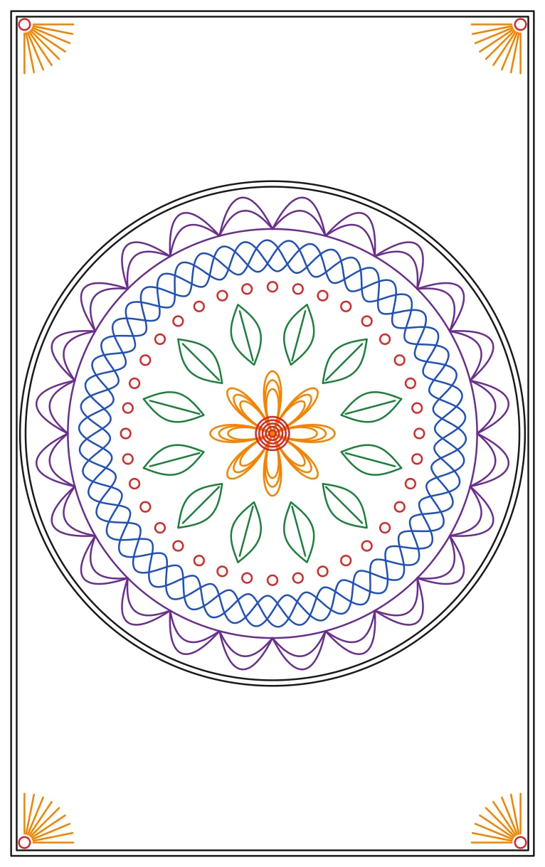
The simulator runs the same firmware code on a computer, with a 3D view and an LCD in the browser. Plotstudio can connect to it in place of the plotter. The repository also has sample G-code, with a six-pen mandala.
See the README for the commands, and the full guide for the firmware, the software, and the calibration.
The six-pen test
The mandala sample uses the full 245 × 390 mm travel and six pen changes.
Build it
Drag to turn · scroll to zoom · right-drag to pan
-
01
Print the parts
- Fit tests: rail, slider, and wheel strip
- Y carriage, left
- Y carriage, right
- X plate
- Pen carriage
- Pen slider
- Y motor bracket, left
- Y front base, left
- Y idler fork
- X idler fork
- Y chain anchor
- Print the three fit tests first.
- Slide the fit slider onto the fit rail. It must slide by its weight, with no side play.
- Put a V-wheel in each hole of the fit wheel strip. Lay the strip across the end of a frame rail.
- Turn the eccentric spacer. Both wheels must grip the slots before the eccentric reaches its end.
- Print the other parts in the orientation of each STL, with supports off.
Tip If a fit test is tight or loose, change the clearance in
hardware/shape.pyand print it again. The build guide PDF gives the values. -
02
Install the heat-set inserts
- Set the iron to 220 °C.
- Put a long M5 insert in the front outer wheel boss of each Y carriage. Push it straight down until its top is flush.
- Put a long M5 insert in the bottom wheel boss of the X plate.
- Put an M3 insert in each standoff of the two front bases.
- Put an M3 insert in each standoff of the X endstop wall on the left Y carriage.
Tip Let each part cool for one minute. Then turn a screw in and out once.
-
03
Put the Y carriages on the rails
- Y carriage, left
- Y carriage, right
- Creality CR-10 V3, dismantled
- M5 socket head screw kit, with nuts
- M5 nyloc nuts and small M5 washers
- Front outer wheel: put an M5 × 30 screw up through a wheel and a 6 mm spacer into the insert.
- Back outer wheel: put an M5 × 35 screw up through a wheel and an eccentric spacer. Put a nyloc nut on top.
- Put an M5 × 35 screw down through the inner boss.
- Stand the frame on the table. Set each carriage on its rail from above, the outer wheels in the outer side slot.
- Put a 6 mm spacer, the inner wheel, and a nyloc nut on the inner screw.
- Turn each eccentric until the play is gone. The carriage must still roll freely over the full length.
- Make the two diagonals of the frame equal. Then tighten the bar screws.
Caution Too much preload makes flat spots on the wheels. Stop when the play is gone.
-
04
Mount the Y motors
- Y motor bracket, left
- Y motor bracket, right
- GT2 20T pulley, 5 mm bore
- M3 socket head screw kit, 6 to 30 mm, with nuts
- M5 socket head screw kit, with nuts
- M5 drop-in T-nuts for 2020
- Hold a 42-40 motor on the outer face of each bracket, the shaft to the inside. Put in four M3 × 10 screws from the inside.
- Put a GT2 pulley on each shaft. Line up its teeth with the inner top slot of the rail. Tighten the set screws on the flat.
- Turn two M5 T-nuts into the back face slot of the back bar, near each end.
- Screw each bracket to the back bar with two M5 × 12 screws.
- Plug in each motor cable. It runs on the table behind the frame.
Tip Fit the motor screw that the bar hides before the bracket goes on the bar.
-
05
Fit the front bases, the Y idlers, and the endstops
- Y front base, left
- Y front base, right
- Y idler bracket, left
- Y idler bracket, right
- Y idler fork
- GT2 20T toothed idler, 5 mm bore
- M3 heat-set inserts, 5.7 mm
- Push an M3 nut into the slot of each Y idler fork.
- Hold an idler between the cheeks, a small washer on each side. Put an M5 × 30 screw through and tighten the nyloc nut.
- Screw a front base on each end of the front bar with two M5 × 12 screws in T-nuts.
- Hold an idler bracket under the two lips. Put an M3 × 12 screw down through the inner lip.
- Set each fork in its bracket. Put an M3 × 20 tension screw through the end wall. Turn it two turns only.
- Screw a Y endstop board on each front base with two M3 × 8 screws, the switch to the back.
Tip Home is the front left corner. A fin on each carriage plate pushes the lever of its switch.
-
06
Tie on the base board
- Hold the base board on the back face of the back bar, 71 mm from the left end.
- Put a 4 mm nylon standoff under each of its two holes.
- Put a cable tie through each hole and its standoff, round the bar. Pull the ties tight.
- Plug in
Y(left motor),Z1(right motor),Y-(left endstop), andZ-(right endstop). - Push the big 2 × 8 plug into the header, pointing up.
Tip Lay the endstop wires in the bottom slots and press the slot cover strip over them.
-
07
Build the X plate
- X plate
- Pen carriage
- M3 socket head screw kit, 6 to 30 mm, with nuts
- M5 socket head screw kit, with nuts
- M5 nyloc nuts and small M5 washers
- Hold the pen carriage on the front of the X plate. The three wheel bosses go through its round holes.
- Put four M3 × 12 screws from the back through the plate into the pen carriage. Do not overtighten them.
- Top left wheel: an M5 × 30 button head through the wheel and a 6 mm spacer. Put a nyloc nut on the front.
- Top right wheel: an M5 × 35 button head through the wheel and the eccentric spacer. Leave its nut loose.
- Bottom wheel: an M5 × 25 button head through the wheel and a 6 mm spacer into the insert.
-
08
Put the beam on the carriages
- M5 drop-in T-nuts for 2020
- M5 socket head screw kit, with nuts
- M3 socket head screw kit, 6 to 30 mm, with nuts
- Slide the X plate onto the beam from one end. The top wheels go in the top slot, the bottom wheel in the bottom slot.
- Turn the eccentric of the top right wheel until the plate has no play. Tighten its nut.
- Turn an M5 T-nut into the back slot of the beam, 14 mm from each end.
- Lay the beam on the two saddles, the pen carriage to the front.
- Screw the beam to each carriage with one M5 × 12 screw through the back wall of the saddle.
- Screw the X endstop board on the X endstop wall with two M3 × 8 screws.
Tip Keep the top and the bottom slots of the beam free. The X belt runs in them.
-
09
Mount the X motor and the X idler
- Put a GT2 pulley on the shaft of the 42-34 motor. Do not tighten it yet.
- Hold the motor behind the left beam end, the shaft to the front through the motor wall. Put in three M3 × 10 screws from the front.
- Slide the pulley until its teeth are on the beam center line. Tighten the set screws.
- Push an M3 nut into the slot of the X idler fork. Put the idler and two small washers in the fork on an M5 × 30 screw and a nyloc nut.
- Set the fork in the seat past the right beam end. Put the M3 × 20 tension screw through the end wall. Turn it two turns only.
Tip The X motor rides on the gantry. The shorter 42-34 keeps the moving mass low.
-
10
Tie on the head board
- Hold the head board on the back face of the beam, 96 mm from the left side of the frame, the big header up.
- Put a 4 mm nylon standoff under each hole. Put a cable tie through each hole and standoff, round the beam.
- Plug in
X(X motor),X-(X endstop), and the servo lead onBL_T. - Push the big 2 × 15 plug into the header from the top. Keep the cable straight for 35 mm.
Caution The two ties go round the beam. Push the X plate past them by hand before you power the motors.
-
11
Crimp and fit the belts
- Cut two Y belts about 1200 mm long and the X belt about 950 mm long.
- Fold one end back 20 mm, teeth to teeth. Crimp a clip over the two layers, 1.5 mm from the fold.
- Crimp the second clip 1135 mm from the first fold on each Y belt, and 898 mm on the X belt. Cut off the tail.
- Turn each tension screw out to the end of its travel.
- Y belts: lay each belt round its pulley and idler, teeth inside. Drop the clips into the clamp blocks of the carriage from the top.
- X belt: feed it through the top slot of the beam, round the pulley, and back through the bottom slot. Push the clips into the X plate from the back.
- Turn each tension screw in until its belt is tight.
Tip If a belt is too long, crimp a new clip closer to the other clip.
-
12
Connect the control box
- Stand the control box on the table, left of the frame, the LCD to the front.
- Tie the head cable to the back of the beam. Tie the base cable along the back bar.
- Plug the two cables into the box. Check the mains voltage setting of the supply.
- Connect the USB port of the box to the computer. Flash the plotter firmware.
Caution Keep the control box off until you complete the wiring checks in the full guide.
-
13
Lay in the moving cables
- Y chain anchor
- Drag chain, openable, 10 × 20 mm inside, R28
- Split wire loom, 1/2 inch
- Cable ties, 2.5 mm
- Screw the chain anchor at the back left corner. One M5 × 12 screw goes up into a T-nut in the bottom outer slot of the rail.
- Open the links of the drag chain. Lay in the head harness. Close the links.
- Bolt the fixed end link to the anchor and the moving end link to the tab of the left carriage, with two M3 × 10 screws each.
- Cut the split loom to 295 mm. Push the servo lead into it.
- Tie the loom through the slot at the top left of the X plate.
- Lead the loom over the beam. Tie its other end to the head harness, above the big plug.
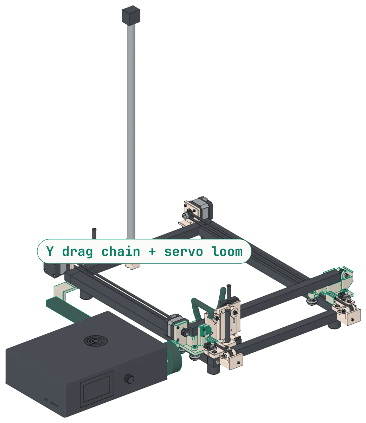
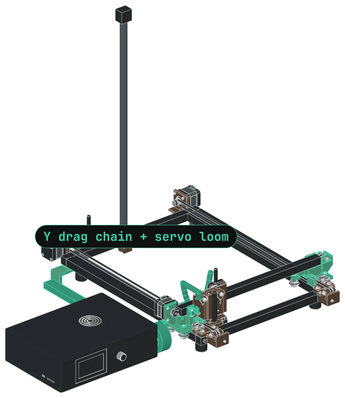
Tip The loop of the loom hangs free behind the beam. It needs no printed holder.
-
14
Fit the servo
- Push the servo into its pocket, the shaft at the bottom. The wire goes out through the slot.
- Put the two servo screws through the tabs. Plug the servo into the servo lead.
- Send
M5(pen up), thenM3(pen down). Leave it at pen down. - Put the horn on the spline. The arm points at the tab of the slider, 10° below level.
Tip Tune the pen up and pen down angles with the knob menu.
-
15
Put in the pen slider and the pen
- Push an M3 nut into the slot in the top of the slider. Turn the M3 × 20 clamp screw in a few turns.
- Slide the slider onto the dovetail rail of the pen carriage from the top.
- Send
M3(pen down). Put the pen in the V bore until its tip touches the paper. - Tighten the clamp screw.
Tip Round pens of 8 to 15 mm fit the V bore. The weight of the slider and the pen is the pen force.
-
16
Stand up the camera pole (optional)
- Camera pole foot
- M6 × 16 socket head screw
- M3 socket head screw kit, 6 to 30 mm, with nuts
- M5 drop-in T-nuts for 2020
- Turn two M5 T-nuts into the back face slot of the back bar, at the center.
- Put the M3 nut and the M3 × 16 collar screw in the ears of the foot. Leave the screw loose.
- Put the pole in the socket. Put the M6 × 16 screw up through the floor into the pole end.
- Screw the foot to the back bar with two M5 × 12 screws. Tighten the collar screw.
- Tie the USB cable of the webcam to the foot and to the pole.
-
17
Home and plot a square
- Turn on the control box. Connect its USB port to the computer.
- Send
M119. Push each endstop by hand and check that it changes. - Send
G28. Both Y sides go to the front switches. This squares the gantry. - Plot
samples/square.gcode. Measure the square: it must be 40 × 40 mm.
Tip The full guide has the calibration and the first plots.
Downloads
- Build guide (PDF)PDF
- Full guide: hardware, firmware, software (PDF)PDF
- Y carriage, left (STL)STL
- Y carriage, right (STL)STL
- X plate (STL)STL
- Pen carriage (STL)STL
- Pen slider (STL)STL
- Y motor bracket, left (STL)STL
- Y motor bracket, right (STL)STL
- Y front base, left (STL)STL
- Y front base, right (STL)STL
- Y idler bracket, left (STL)STL
- Y idler bracket, right (STL)STL
- Y idler fork, print 2 (STL)STL
- X idler fork (STL)STL
- Y chain anchor (STL)STL
- Camera pole foot (STL)STL
- Fit test, rail (STL)STL
- Fit test, slider (STL)STL
- Fit test, wheel strip (STL)STL
Licenses and credits
The code is MIT. The designs, the print files, and the documents are © 2026 Jeremy Collins under CC BY 4.0. The slicer profiles in profiles/ are a copy of the Printdeck profiles and keep their AGPL-3.0.
The hole positions of the CR-10 carriage plate come from the model carriage_plate_Bear.step by Bear on Printables, under CC BY.
The text in the samples uses the Hershey fonts, which are in the public domain. The samples read them with the Hershey-Fonts Python package by Attila Kolinger (MIT).
Creality, CR-10, and LulzBot are trademarks of their owners. This project is not affiliated with them.