Projects / 3D print · In progress
Bittle X Platform + Pi Add-on
The 3D-printed platform and Pi pod for LineChef's Bittle X robot project.
- Printed parts
- 6
- Tools
- None
- Add-on weight
- 135 g
- Skill
- Intermediate
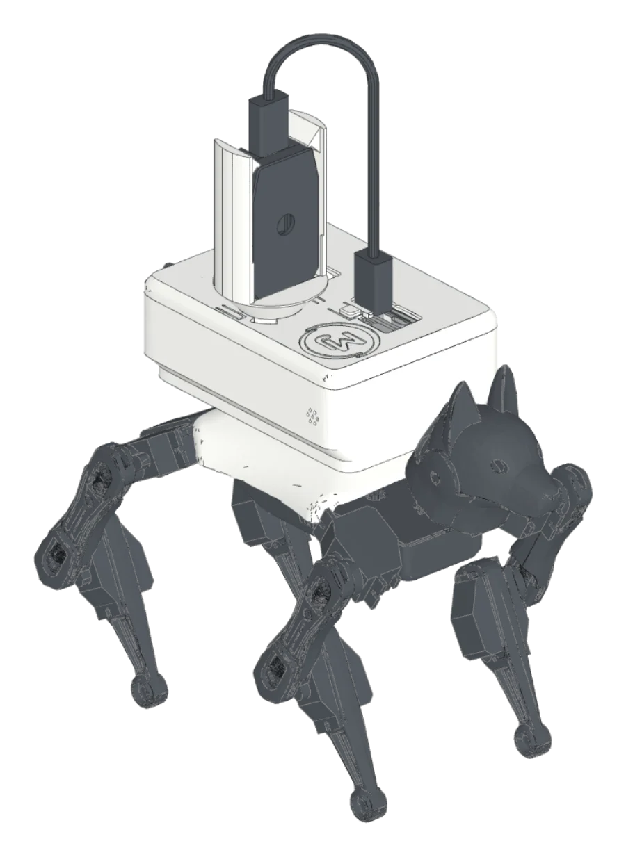
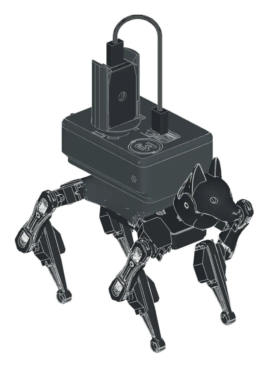
Overview
This is the printed hardware for LineChef's BittleX project, which teaches a Bittle X to walk, see, talk, and remember. My part is the 3D model and the printed build: the platform and the pod. The electronics, the wiring, and the software are LineChef's.
The platform is the stock Petoi back cover with four teardrop pegs on its flat top. It replaces the stock cover. The inside does not change, so the BiBoard and the touch sensor fit as before.
To attach an add-on, put it on the pegs, slide it 7 mm forward, and it clicks. Two spring beams at each peg push it into a V stop, so it does not rattle. The teardrop shape means it goes on one way only.
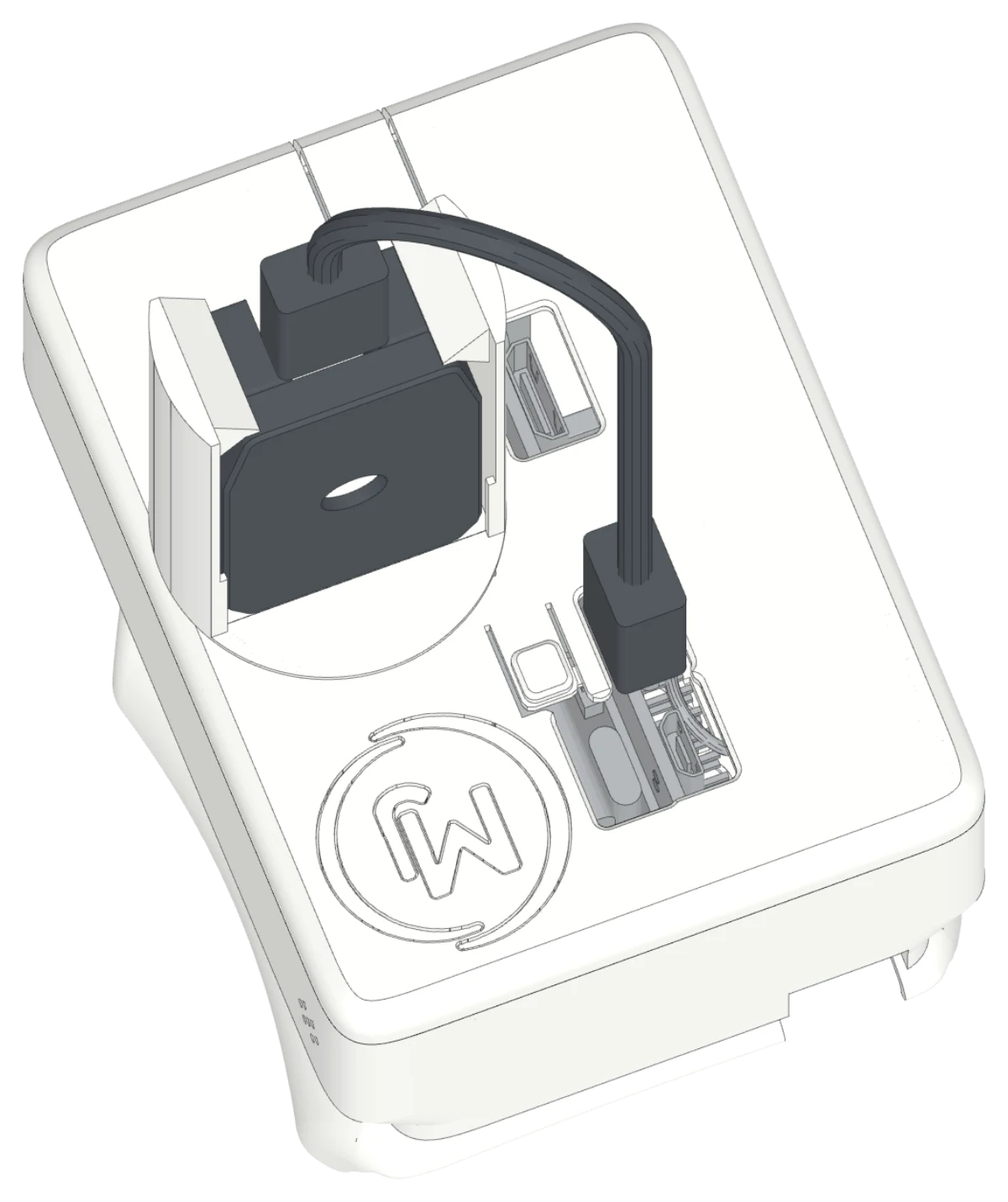
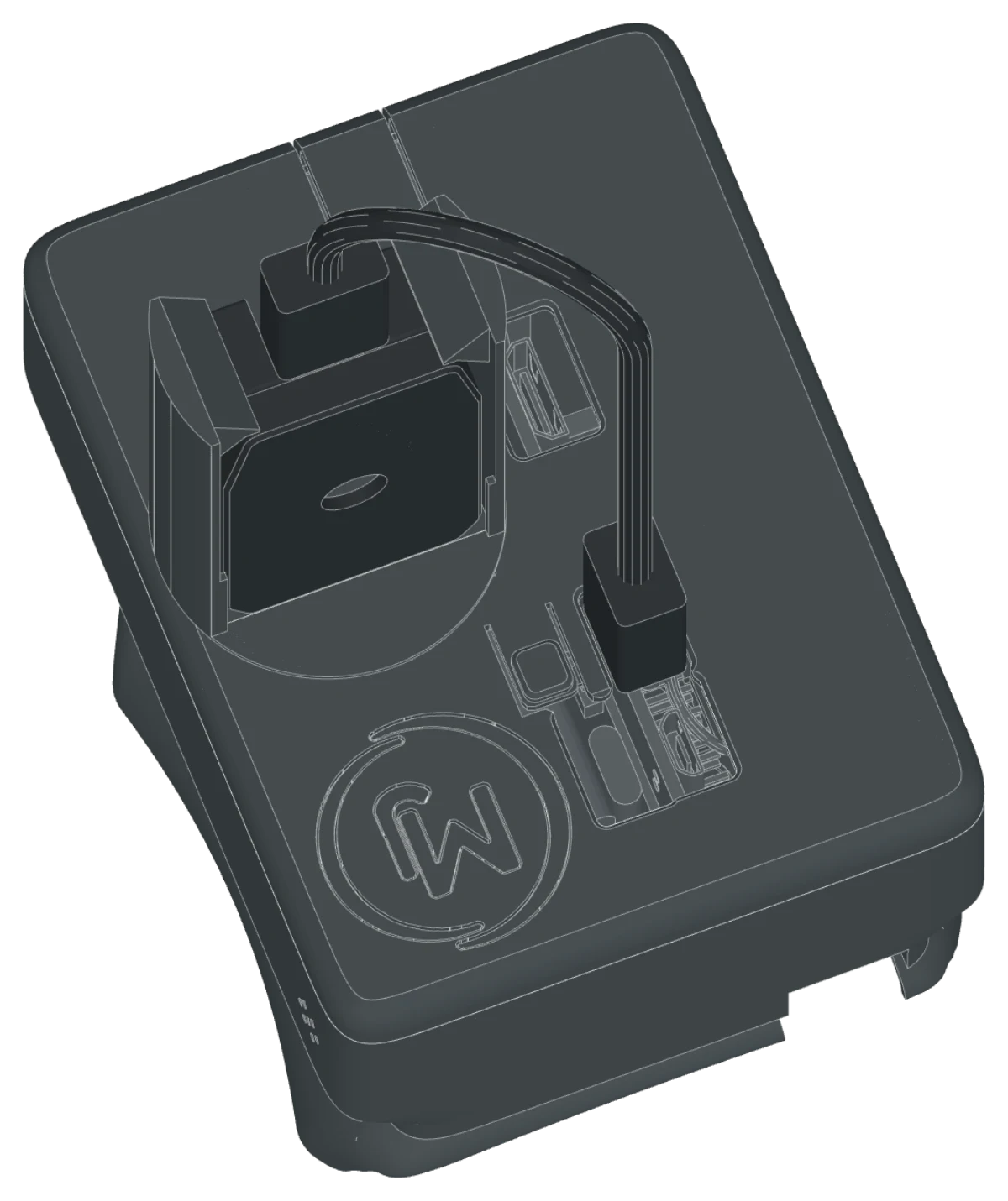
The pod is the first add-on. It is a rounded case with places for a Raspberry Pi Zero 2 W and a PiSugar S battery, an amp and speaker at the rear, a microphone on the side, and the Petoi AI Vision Module on a twist-lock mount.
Every printed part prints without supports. A slide-on top panel has openings shaped to each plug, a window over the power switch, and a large button over the PiSugar button.
What you need
| Part | Qty | Type | Get it |
|---|---|---|---|
| Platform cover PLA, stands on its rear end, 11 g | 1 | Download | |
| Pod body PLA, floor on the bed, 40 g | 1 | Download | |
| Top panel PLA, second color, top on the bed. Slice the 3MF. | 1 | Download | |
| Button cap PLA, white, top on the bed | 1 | Download | |
| Logo inlays PLA, white and red | 2 | Download | |
| Camera mount PLA, second color, standing up. Keep the brim. | 1 | Download | |
| Petoi Bittle X robot dog | 1 | Have | Petoi ↗ |
| Raspberry Pi Zero 2 W With a soldered 40-pin header and a pin-fin heatsink | 1 | Buy | Raspberry Pi ↗ |
| PiSugar S battery board, 1200 mAh The board in LineChef's parts list | 1 | Buy | PiSugar on Tindie ↗ |
| NS4168 I2S amplifier board NULLLAB, 38.4 × 22.4 mm, PH2.0 connectors. Sold as a kit with the speaker. | 1 | Buy | Amazon ↗ |
| Speaker, 3 W, 4 Ω NULLLAB, 28 × 15 mm body with side wings, PH2.0 plug. Comes in the amp kit. | 1 | Buy | Amazon ↗ |
| SPH0645 I2S MEMS microphone HiLetgo or Adafruit breakout, 12.5 × 16 mm | 1 | Buy | Adafruit ↗ |
| Petoi AI Vision Module In its Petoi case | 1 | Buy | Petoi ↗ |
| Dupont jumper wires 3 female-to-male, 6 female-to-female (10 cm, plus 15 cm for GND and 3V) | 9 | Buy | Amazon, 10 cm set ↗ |
| USB-C to micro-USB cable Short, about 12 cm between plugs | 1 | Buy | Amazon search ↗ |
Tools
- 3D printer — Any bed, the parts are small
- Cura profile “Bittle X” — 0.20 mm layers, no supports, 6-line brim
- Soldering iron — For two short wire splices (BCLK and LRC)
- A drop of glue — To set the amp and the logo inlays
Print settings
- Material
- PLA, two colors plus white and red for the logo
- Layer height
- 0.20 mm
- Supports
- None
- Brim
- 6 lines. Keep it on the camera mount.
- Walls
- 2.0 mm, which Cura slices as 4 lines of 0.5 mm
- Panel
- Slice
pod_panel.3mf. It has a support blocker over the logo pocket.
Electronics and software
The electronics and the software are from LineChef's BittleX project, used with permission: walking by reinforcement learning, on-device vision, voice conversations with Claude, and memory. The hardware notes list the parts and the power setup.
Wiring
This wiring is from LineChef's G2 wiring guide, which has the full diagrams. The Pi talks to the BiBoard over serial, and to the amp and mic over I2S. Plug the wires in this order: the splices, the Pi ends of the BiBoard jumpers, the amp cable, the mic jumpers, then the BiBoard ends.
BiBoard TX2 / RX2 / GND → Pi pins 10 / 8 / 6. TX and RX cross. Do not wire the BiBoard +5V. The PiSugar powers the Pi.
Amp V / G → Pi pins 2 / 14 (5V and GND).
Mic 3V / GND / SEL → Pi pins 1 / 9 / 39. SEL to GND selects the left channel.
BCLK → Pi pin 12 (GPIO18), through a soldered splice to both the amp and the mic.
LRC → Pi pin 35 (GPIO19), through a second splice to both boards.
Amp DIN → Pi pin 40 (GPIO21). Mic DOUT → Pi pin 38 (GPIO20).
The speaker plugs into the 2-pin PH2.0 socket at the rear end of the amp.
Build it
Drag to turn · scroll to zoom · right-drag to pan
-
01
Print the parts
- Install the “Bittle X” Cura profile. It sets 0.20 mm layers, no supports, and a 6-line brim.
- Print each part in the orientation listed under Print settings. The STLs are already turned.
- Print the panel from
pod_panel.3mf, not the STL.
Tip The body walls are vertical, and the holes are teardrops. They print clean with no bridges.
-
02
Fit the platform cover
- Take the stock back cover off your Bittle X.
- Put the platform cover on in its place. It fits the BiBoard and the touch sensor the same way.
- The notch at the front left lets the head camera cable out.
-
03
Click on the empty body
- Put the empty body on the four pegs, 7 mm behind its final place. The grille faces the rear.
- Slide it 7 mm forward until it clicks.
- The BiBoard header now sits in the notch at the front of the left well.
Tip To remove the body later, slide it 7 mm to the rear and lift it.
-
04
Drop in the speaker
- Push the speaker down into the two side grooves at the rear of the body.
- The speaker body faces the rear grille.
-
05
Fit the microphone
- Plug the six jumpers onto the mic header. Use the 15 cm jumpers for GND and 3V.
- Drop the mic into the slots on the right wall near the front. The port faces the wall and the header faces forward.
- The panel holds the mic in place later. No tools needed.
-
06
Fit the amp
- Plug the flat I2S cable into the front end of the amp, and the speaker into the rear end.
- Put the bottom edge of the amp into the slot along the right wall, parts facing in.
- Tilt the top edge under the two nubs, and set it with a drop of glue.
- Let the amp cable hang out of the top for now.
-
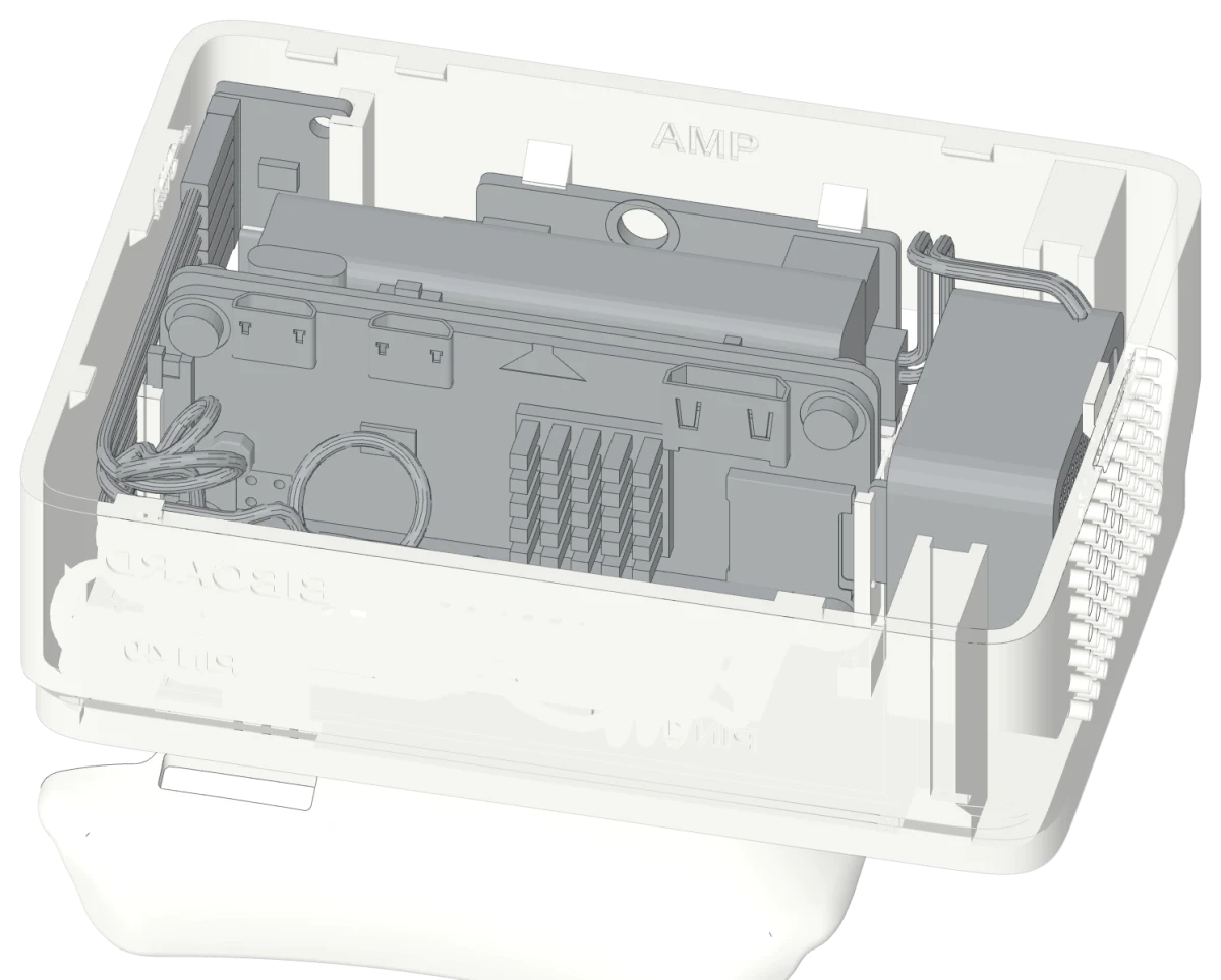
07
Drop in the Pi stack
- Stack the Pi Zero 2 W on the PiSugar S with its screws.
- Push the stack down into the two end grooves. Ports and the PiSugar controls face up. The SD card faces the rear.
-
08
Plug in the wires
- Follow the order and the pin table in Wiring above, from LineChef's guide. Plug one wire at a time.
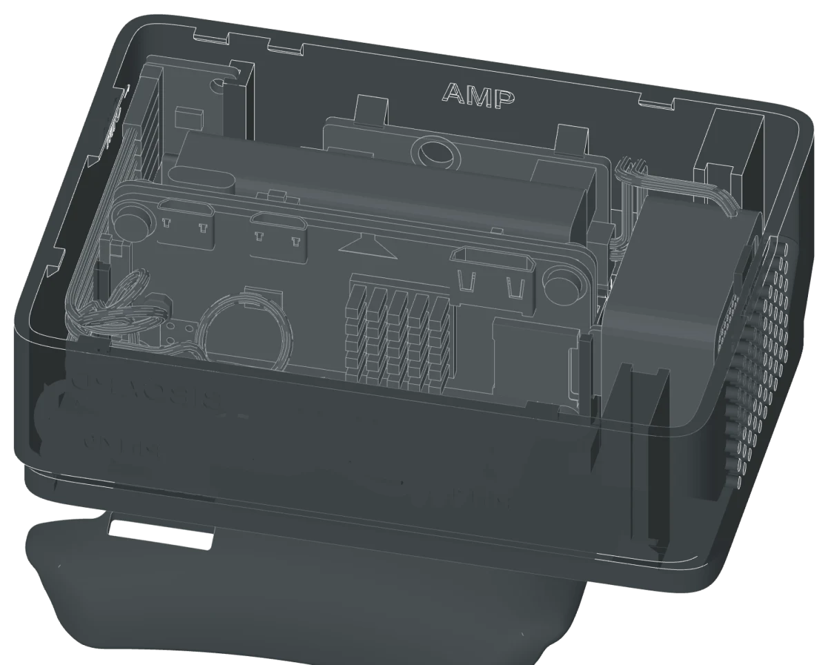
- Labels in the body show where each part goes: MIC, AMP, SPEAKER, BIBOARD, PIN 1, and PIN 40.
- Push the BiBoard plugs onto the header at the front left last. All wires stay inside the body.
-
09
Prepare the top panel
- Press the post of the white button cap into the round hole in the panel tongue. Stop when the cap sits flat.
- Glue the two logo inlays into the pocket in the front right corner: white at the left, red at the right.
-
10
Slide on the panel
- Put the panel down 5 mm behind its place.
- Slide it forward until the latch clicks. The hooks under the panel go under the lugs in the walls.
Tip To open: lift the rear edge at the finger notch, slide the panel 5 mm to the rear, and lift it.
-
11
Mount the camera
- Turn the camera mount 40° counterclockwise from its final place, seen from above.
- Put it into the round socket in the panel with the two lugs through the keyways.
- Turn it 40° clockwise until it clicks and stops.
- Push the camera case down between the brackets, lens forward and USB port up, until the hooks click.
Tip To point the lens to the rear, turn the mount end for end first. It locks the same way.
-
12
Connect the camera
- Plug the USB-C end into the top of the camera.
- Plug the micro-USB end into the Pi data port. The cable arches to the rear over the panel.
- Charge the PiSugar, then press the large tongue on the panel to turn it on.
Downloads
- Build guide, 15 steps (PDF)PDF
- Platform cover (STL)STL
- Pod body (STL)STL
- Top panel (Cura 3MF)3MF
- Button cap (STL)STL
- Logo inlay, white (STL)STL
- Logo inlay, red (STL)STL
- Camera mount (STL)STL
- Head-off camera base (STL)STL
- Head-off camera cradle (STL)STL
- Starter plate for your own add-on (STL)STL
- Platform interface spec (PDF)PDF
- Platform interface (JSON)JSON
- Pi add-on guide (PDF)PDF
- Cura profileCURAPROFILE
Licenses and credits
The 3D model, drawings, and documents are © 2026 Jeremy Collins under CC BY 4.0.
The electronics, the wiring, and the software are from LineChef's BittleX, used with permission. The text of the Electronics and Wiring sections follows LineChef's documents.
The robot in the 3D view comes from the Petoi ROS model of Bittle (MIT).
The platform cover adds pegs to the Petoi Bittle_Cover_with_hole_for_Pi.stl from PetoiCamp/NonCodeFiles. Petoi publishes it with no stated license, and all rights to it stay with Petoi.
The PiSugar models are GPL-3.0. Bittle and Petoi are trademarks of Petoi LLC. This project is not affiliated with Petoi.